The minimum rotor yoke height Hry is the same as the stator yoke height Hsy. The height should be large enough to avoid saturation. This also has advantages of reducing core loss and reluctance.
The minimum yoke heights are given by [10]:
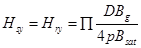 (Eq. 3.9)
Airgap Length
The airgap length has a minimum value limited by the manufacturing tolerances; this value is typically in the range of 0.3mm to 1mm. In this design 0.5mm is chosen to be the airgap length.
Generator Length
The generator length is estimated to be 95mm; this is approximated from flux required to give the output voltage of the generator.
Airgap Flux Per Pole
In a radial machine, the flux per pole is given by:
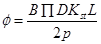 (Eq. 3.10)
where B is the average airgap flux density, D is the rotor inner diameter, L is the generator length, Kst is the lamination stacking factor and p is the pole pairs.
For this design the average flux density per pole Bgav is equal to the peak flux density Bg since the magnet arc is close to 180 degrees. Therefore the peak airgap flux is estimated to be 0.5T at the airgap and Kst is assumed to be 0.97.
The airgap flux and the lamination stacking factors were estimated from the following dimensions of the loudspeaker magnet:
· Magnet arc = 180 mechanical degrees
· Inner radius = 8mm
· Arc radius = 25mm
· Magnet radial length = 4mm
· Area of one pole = 706.8 μm2
From the above magnet dimensions, the flux per pole in the machine is then estimated to be 1.16 mWb this value is calculated from equation 3.10.
Windings
The stators of most synchronous generators are wound with three distinct and independent windings to generate three-phase power [14]. A simple layer winding was used in this design. Slot per pole per phase was chosen to be 1 and the winding pitch was full pitch.
A. Types of winding
The preferred type of winding is distributed winding as it reduces harmonics and makes better use of the stator or rotor structure. The mmf induced in the airgap is not sinusoidal, to get a pure sinusoidal mmf the number of slots have to be infinity. This means that the distributed winding is expected to have some harmonics.
Induced voltage for the distributed windings is:
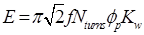 (Eq. 3.11)
Kw is the winding factor and depends on the winding arrangements and has a value less than unity. Distribution factor Kd and a short pitch factor Kp reduces the winding voltage magnitudes but also reduces certain harmonics in EMF and MMF waveforms.
 (Eq. 3.12)
Distributed winding configuration has one slot per pole per phase and its winding factor is equal to 1.
B. Winding arrangement
Single layer winding, where each slot contains one coil side, will be used in this design as it is economical to manufacture and has simpler end connection. Emf and mmf can be modified to reduce harmonics. In a three phase system even harmonics do not appear due to the winding symmetry, the only visible harmonics are the belt harmonics.
C. Winding Pitch
Short pitch is the most commonly used type of winding pitch. It reduces the distorting harmonics and produces a truer sinusoidal wave. The length of the end connection is also reduced thereby saving copper and reducing copper loss in the coil.
The drawback of short pitch winding is that the induced emf in it is smaller than in a full-pitch coil. The reason is that the total flux linking the short-pitch coil is smaller than that of the full-pitch coil.
Number of turns
The number of turns per pole is estimated to be 60 turns from equation 3.11.
The design parameters discussed will be modelled in FEMM in the next chapter to induce the output voltage and flux of the generator.
Дата: 2019-07-24, просмотров: 335.