Figure 2.8 below shows the artist impression of the wind generator designed exclusively for Ga-Rampuru village.
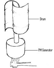
Figure 2.8 Ga-Rampuru wind generator
The following chapters describe the steps taken by the author to investigate the performance of a synchronous permanent magnet machine constructed using recyclable loudspeaker magnets.
Chapter 3. Generator Design
A brief background
This chapter will detail a simple procedure undertaken to design the wind generator from recyclable materials. Permanent magnet machines are preferred for this application as they reduce the excitation losses significantly and hence a substantial increase in the efficiency of the machine. In addition, permanent magnet machines are simple to construct and maintain [10].
The most common wind turbine systems are three blades rotating on a horizontal axis coupled to an alternator to generate electricity, which could be used to for battery charging. For a picture of a typical basic wind turbine system refer to figure 2.1 in chapter 2.
A normal two- pole synchronous permanent magnet generator will be designed and its performance will be analysed. Then recyclable loudspeaker magnets found in the rural area of Ga-Rampuru village will be used to substitute the standard commercial magnets in the generator. The performance of the new generator will be analysed to understand the effect of the loudspeaker magnets on the generator performance.
For this investigation, matching the refrigerator load in chapter 1 will not be a priority.
This chapter will start with outlining the desired generator specification and then the generator will be designed thereafter. To design the generator the permanent magnet properties will be discussed to understand their effect on the generator performance and losses due to these magnetic materials will also be investigated. And then, all the variables that are necessary to construct and design a generator geometry will also be discussed.
Throughout this thesis the generator performance will be tested under no-load conditions.
Generator specifications
In this thesis, a generator with the following specifications will be designed and modelled in FEMM, a finite element package:
· Output power = 36W @ 12V
· Number of phases = 3
· Number of poles = 2
The choice of the above dimensions of the generator was influenced by the following consideration:
·Induced output voltage, 12V is standard voltage that is used in many applications. For example it is suitable to charge a battery. Batteries are suitable to power a wide range of rural appliances and instruments especially in remote areas of South Africa [11].
·The generator must be easily assembled and manufactured so that the rural artisans with little training can be able to assemble this generator.
The following design procedure will be followed:
1. A simple two-pole synchronous permanent magnet generator will be designed using available standard commercial magnets such as ceramics, alnicos and rare-earth magnets.
2. The effects of the above magnets on the performance of the generator will be investigated.
3. The magnets from a loudspeaker that was randomly picked in the village will then be used in the design and the performance will also be investigated.
The designs above will be modelled using FEMM, a finite element package. The main reason for using FEMM is to observe the output induced voltage of the generator. This will be the method of how the performance of the generator will be monitored.
Generator basic principle
The main function of a generator is to supply power to the load, in order to do so; voltage has to be generated at the terminals. The generator principle is based on Faraday’s law of induction [10]:
 (Eq. 3.1)
where e is the instantaneous voltage,  is the flux linkage and t is the time.
The law states that for voltage to be induced in a winding, the magnetic flux has to change relative to the winding. This means that the flux linkage is changing and the conductor is fixed or stationary. The flux linkage is the total flux,  , linking all conductors in a winding with N turns. Therefore the flux linkage is given by:
 (Eq. 3.2)
To generate voltage in practice, a mechanical motion and a source of magnetic flux must be present. The mechanical motion can be linear or rotational, in this thesis the motion is rotational and provided by the wind turbine. The source of flux is permanent magnets.
Дата: 2019-07-24, просмотров: 300.