Planning of mobile complete set for a rural wind generator
Abstract
The aim of this thesis is to alleviate the chronic lack of electricity supply in the rural South African areas by designing a portable wind generator kit.
An extensive assessment on the rural village of Ga-Rampuru, in Limpopo Province, was conducted, to investigate the present needs, as well as the availability of resources both human and material that would be needed to construct and assemble the system. From the inventory of recyclable materials found during the investigation the author was more inclined to suggest the design of a wind turbine that could be assembled and maintained by the local artisans.
A two pole permanent magnet synchronous generator was designed using standard commercial magnets, which were later replaced by recyclable loudspeaker magnets that were found in the village. This was done to compare the output of the generator in both cases. All the designs were modelled in FEMM, a software package, to estimate the induced voltage and flux of the generators.
Using standard commercial magnets the simulated voltage and flux levels were 9.4, 5.1, 3.6V and 0.0489, 0.0186, 0.0175 Wb, respectively. Assuming a generator current rating of 1 amp this would yield 36 watts at the estimated average wind speed of 4 meters per second.
Then when these were substituted with recycled speaker magnets the generator yielded a voltage of 3.5V and a flux of 0.0171Wb. The estimated output power of the recycled generator was estimated to be 10.5W. This compared well with the power output from the commercial magnets generators.
From these preliminary results it is quite apparent that a viable generator can be designed from the recyclable magnetic components. The same design procedure as outlined in this thesis can be used to design larger recycled generators with larger outputs. The design of this wind turbine will obviously have a wide range of positive developmental benefits on the community of Ga-Rampuru.
The next stage was practical construction to validate of the simulation results. This however could not be realised in time.
Chapter 1. Introduction
The subject of the report
The aim of this thesis is to design a simple wind generator kit that can be easily assembled and installed by rural artisans. The kit will use recyclable materials that are found in the rural areas to ensure a cost effective and environmentally sustainable solution.
Resource assessment
The author spent the next three weeks exploring the resources available in Ga-Rampuru that would support the design and sustainable construction of electricity generators.
To begin with Ga-Rampuru has two schools, namely Rampuru primary school and Seokeng secondary school, all which constitute a total population of roughly 1400 pupils. On average 30% of school leavers will continue to tertiary education, some will migrate to urban centres in search for jobs and a substantial number will remain in the village.
This village is endowed with adequate human capacity with intermediate levels of education. These would constitute a source of trainable technicians and potential consumers of locally manufactured products. There are also local mechanics who fix cars and some electrical appliances. These people will be easily trained as they have hands on experience.
Some of the people who left the village for jobs in the cities come back to settle down in the village and build big houses like the one indicated in Fig 2. This clearly indicates that this people can afford the electricity tariffs if they were to be supplied with power.
Moving further around the village there was evidence of old windmills used for pumping water. Figure 3 shows one of the windmills. These windmills operate satisfactorily providing enough water to the villagers. The presence of these windmills in this area is evidence that there is some wind resource in the area.
Further investigations took the author to various waste-dump sites and a range of disused old gadgets that could potentially be re-used, as shown in appendix A, were discovered. These included cables from an old car, loudspeaker magnets, drums and old machines that were used for grinding grain.
The other natural resource in the area (of course) is the sun but from the inventory of recyclable materials found during the investigation it is more inclined to suggest the design of a wind turbine.
Objectives of the report
In light of the above background, the main objective of this thesis is to design a small wind generator for Ga-Rampuru village using recyclable materials found in this village. The idea is to build an easily assembled and manufactured machine that can be build by the rural artisans. This wind generator must of course be cost effective.
The resource assessment of Ga-Rampuru village is conducted in order to investigate the present needs, as well as the availability of resources both human and material that would be needed to construct and assemble the wind turbine using recyclable materials. Furthermore, the resource assessment analyses lead to an appropriate wind generator design specifically for Ga-Rampuru village.
Method of investigation
The investigations were conducted in July 2006 at Ga-Ramrupu village in Limpopo province. The author collected information regarding this village in the following manner:
1. The author grew up in Ga-Rampuru village and therefore knows the problems and challenges that the villagers face on a day-to-day basis living without electricity. This was an advantage in terms of moving around the village doing the resource assessment analysis.
2. One of the store owners in the village, Mr Morifi was interviewed regarding the issues he faces in supplying power to his store, especially to the refrigerator he has in store. The store owner mentioned that he has to refill the petroleum gas (LPG) in his store every two weeks. He also added that this is very expensive as there are also transport costs involved.
3. Face to face interviews were conducted with some of the villagers where many concerns and challenges were raised. Most of the villagers said that it has been several years since they have been promised to be electrified and nothing has been done to date.
4. The author paid a visit to the Provincial ESKOM office in Pretoria to enquire about any plans to extend the grid to Ga-Rampuru village. The ESKOM Electrification Manager, Jack Bandile was interviewed in this regard.
Plan of development
The report begins with a brief background of the thesis and introduction of the rural area for which the wind generator will be designed for. Then, the remaining project researches are outlined as follows:
· Chapter 2 reviews the design of a small wind generator and after that a wind generator suitable for Ga-Rampuru village is designed using recyclable materials that where found in this village.
· Chapter 3 details the procedure undertaken to design a permanent magnet synchronous generator for Ga-Rampuru village wind turbine.
· Chapter 4, the generator geometry discussed in chapter 3 is modelled in FEMN using recyclable and commercial magnets to analyse and estimate both machine designs.
· Chapter 5 discusses the results found in chapter 4.
· Chapter 6 details all the steps that were taken in an attempt to assemble a prototype of the wind generator.
· Chapter 7 & 8 concludes the discussion based on the analyses and finally presents recommendations.
Background on wind energy
Wind powered systems have been widely used since the tenth century for water pumping, grinding grain and other low power applications [9]. Since then, this has lead to an investigation and attempt to build large wind energy systems to generate electricity.
Wind energy has proven to be cost effective and reliable in the past years. The main development of this technology has been with large wind turbines in the industrialized world, but there is scope to deliver decentralized energy service in the rural areas of developing countries [6].
Furthermore, wind energy is an attractive option to generate electricity since it does not consume fossil fuels nor emit greenhouse gases. The land on which the wind generators are build may also be used for agricultural purposes such as ploughing the land or domestic animal gazing.
During its transition from the earlier day’s wind ‘mills’ to the modern electric generators, the wind energy conversion systems (WECS) have transformed to various sizes, shapes and designs, to suit the applications for which they are intended for [5]. In this chapter, the main components of a simple small wind generator will be investigated and a wind generator suitable for Ga-Rampuru village will be designed using recyclable materials found in the area.
The available wind resource is governed by the climatology of the region concerned and has a large variability from one location to the other and also from season to season at any fixed location [9]. Hence, it is important that the wind generator is designed for a specific area; this will ensure that the wind energy in that specific area is exploited to generate maximum power from the wind.
The blades
Modern wind turbine rotors usually have two or three wooden blades. A larger number of blades would create more turning force (torque), but would not be capable of driving the PM generator fast enough to generate the required voltage, because the rotor would turn more slowly [6]. The rotor blades are designed in such a way that they extract the maximum power from the wind.
Power supplied by the blades to the generator is [7]:
 (Eq 2.1)
where  is the air density (Kg/m3), C is the dimensionless power coefficient and A the area swept by the blades in m3.
In equation 2.1 above, the power drawn from the wind is proportional to the cube of the wind speed. This means that if the wind speed doubles, there is 8 times as much power available from it [7].
A further important parameter is the tip speed ratio. The tip speed ratio is defined as the ratio of the tip of the blade to that of the undisturbed wind velocity entering the blades [11]. The ratio is given by [7]:
 (Eq 2.2)
where R is the radius of the blades, ωr is the rotor speed in rad/s and W the wind speed (m/s).
Multi bladed rotors operate at low tip speed ratios of 1 or 2, where else, one, two or three bladed rotors operate at higher tip speeds of 6 to 10. The power coefficient in equation 2.1 depends on tip speed ratio as shown in figure 2.2. For a particular wind rotor design there exists a tip speed ratio which will produce the maximum value of power coefficient [11].
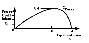
Fig. 2.2 Power coefficient Cp versus tip speed ratio [11]
Permanent magnet generator
Using permanent-magnet generators for small wind turbines is very commonly used world wide. Usually an AC generator with many poles operates between 10-100 Hz. Many configurations use surface mounted three phase permanent magnet synchronous generators with a rectifier connected to the generator terminals. [16]
A simple PM generator consists of the stator, magnet rotor disk and a shaft. The magnet rotor disk is mounted on a bearing hub so that it can rotate on the shaft due to the rotating blades of the wind generator.
The stator has coils of copper wire wound around them, which are accommodated in the slots. Electricity is then generated when the magnets on the rotor disks rotate past the coils embedded in the stator. The magnetic field that is created induces a voltage in the coils [6].
Rotor design
There are two types of rotor configurations commonly used world wide, these are the disk and the cup as shown in figure 2.3 below [20].
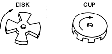
Fig. 2.3 Disk and cup rotor designs
The radius of the rotor primarily depends on the power expected from the turbine and the strength of the wind regime in which it operates [5].
Tower
The main function of the tower is to raise the blades and the generator to a height where the wind is stronger and smoother than the ground level. The wind speed increases with height because of the earth surface [9]. The tower should be high enough to avoid any obstacles such as trees, building, etc. Practical considerations such as expense, safety and maintenance limit the tower to between 10m to 20m [6] above ground level.
The drum
The output of the wind generator depend on the amount of wind swept by the blades, therefore the wind extracting materials in a wind generator are very significant. A plastic drum will be used in this design to extract the wind since it can be easily shaped and carefully balanced to run smoothly. Also, it is resistant to fatigue braking and has a very light weight.
The drum will be assembled as follows:
1. The top and the bottom part of the drum will be cut carefully by using a knife or pair of scissors to make a cylinder with open ends.
2. The cylindrical drum is then cut length-wise into two equal halves.
3. The two halves are then glued together similar to the drum shown in figure 2.4.
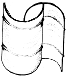
Figure 2.4 An S-shaped drum
To prevent the over speeding of the drum, the permanent magnet generator should always be connected to a battery or other electrical load. If this is not done the wind turbine will become noisy and may vibrate so much that some parts come loose and fall to the ground [6].
Magnet rotor disk
After a tour around the village neighbourhood dumpsites it was discovered that there are many discarded loud-speakers that are no longer in use in the village. These loud-speakers have permanents mounted to their back. Since the PM generator requires magnets, these loud-speakers will be recycled and the magnets on them will be used in this design. Figure 2.5 shows one such magnet that was found in the village.
There are many factors such as heat, radiation and strong electrical currents that can affect the strength of a magnet [8], especially in such discarded state. These factors will be discussed later to investigate exactly how much surface magnetic flux density these magnets loose in the dumpsites.
And later on in this thesis the performance of a PM wind generator designed using standard commercial magnets will be compared to a generator using the recycled loudspeaker magnets as substitutes.
Designing a generator using the speaker magnets will pose the following challenges due to their shape and strength:
· How does one design a machine with these magnets?
· Do they have to be smashed and aligned to work?
· Or should they be used the way they are?
· How much flux density do these magnets have, in other word, can they give out any power when used in the generator design?
· Can different magnet types be used on one machine? As this magnets are picked randomly in the rural area.
Rotor Disk
A cylindrically shaped rotor is preferred as it allows the proper distribution of flux over the armature surface as the field coils are spread over the periphery of the cylindrical rotor. Hence, a brake plate from an old car like the one in figure 2.6 will be used as the rotor in this design to hold and house the magnets.
Distribution cables
All the cabling that will be required in the construction of the wind generator was found in an old car in the village [See figure 2.7].
Chapter 3. Generator Design
A brief background
This chapter will detail a simple procedure undertaken to design the wind generator from recyclable materials. Permanent magnet machines are preferred for this application as they reduce the excitation losses significantly and hence a substantial increase in the efficiency of the machine. In addition, permanent magnet machines are simple to construct and maintain [10].
The most common wind turbine systems are three blades rotating on a horizontal axis coupled to an alternator to generate electricity, which could be used to for battery charging. For a picture of a typical basic wind turbine system refer to figure 2.1 in chapter 2.
A normal two- pole synchronous permanent magnet generator will be designed and its performance will be analysed. Then recyclable loudspeaker magnets found in the rural area of Ga-Rampuru village will be used to substitute the standard commercial magnets in the generator. The performance of the new generator will be analysed to understand the effect of the loudspeaker magnets on the generator performance.
For this investigation, matching the refrigerator load in chapter 1 will not be a priority.
This chapter will start with outlining the desired generator specification and then the generator will be designed thereafter. To design the generator the permanent magnet properties will be discussed to understand their effect on the generator performance and losses due to these magnetic materials will also be investigated. And then, all the variables that are necessary to construct and design a generator geometry will also be discussed.
Throughout this thesis the generator performance will be tested under no-load conditions.
Generator specifications
In this thesis, a generator with the following specifications will be designed and modelled in FEMM, a finite element package:
· Output power = 36W @ 12V
· Number of phases = 3
· Number of poles = 2
The choice of the above dimensions of the generator was influenced by the following consideration:
·Induced output voltage, 12V is standard voltage that is used in many applications. For example it is suitable to charge a battery. Batteries are suitable to power a wide range of rural appliances and instruments especially in remote areas of South Africa [11].
·The generator must be easily assembled and manufactured so that the rural artisans with little training can be able to assemble this generator.
The following design procedure will be followed:
1. A simple two-pole synchronous permanent magnet generator will be designed using available standard commercial magnets such as ceramics, alnicos and rare-earth magnets.
2. The effects of the above magnets on the performance of the generator will be investigated.
3. The magnets from a loudspeaker that was randomly picked in the village will then be used in the design and the performance will also be investigated.
The designs above will be modelled using FEMM, a finite element package. The main reason for using FEMM is to observe the output induced voltage of the generator. This will be the method of how the performance of the generator will be monitored.
Generator basic principle
The main function of a generator is to supply power to the load, in order to do so; voltage has to be generated at the terminals. The generator principle is based on Faraday’s law of induction [10]:
 (Eq. 3.1)
where e is the instantaneous voltage,  is the flux linkage and t is the time.
The law states that for voltage to be induced in a winding, the magnetic flux has to change relative to the winding. This means that the flux linkage is changing and the conductor is fixed or stationary. The flux linkage is the total flux,  , linking all conductors in a winding with N turns. Therefore the flux linkage is given by:
 (Eq. 3.2)
To generate voltage in practice, a mechanical motion and a source of magnetic flux must be present. The mechanical motion can be linear or rotational, in this thesis the motion is rotational and provided by the wind turbine. The source of flux is permanent magnets.
Types of magnets
There are three main types of magnets that can be found, these are [10]:
1. ALNICO (Aluminium, nickel, cobalt, etc.)
These type of magnets poses high magnetic remanent flux density and low temperature coefficients. The coercive force is very low and the demagnetization curve is extremely non-linear. Therefore, it is very easy to magnetize and demagnetize ALNICO magnets.
2. Ceramic or Ferrites (BaFe203 or SrFe203)
A ferrite has a higher coercive force than Alnico, but at the same time has a lower remanent magnetic flux density. Their main advantage is their low cost and very high electric resistance.
3. Rare – earth (SmCO, NdFeb-Neodynium Iron Boron)
These are one of the strongest types of magnets available. They poses high remanent flux density, high coercive force, high energy product, linear demagnetization curve and low temperature coefficients. The main disadvantage is the cost.
High performance rare-earth magnets have successfully replaced Alnico and Ferrites magnets in all applications where the high power-to-weight ratio, improved dynamic performance or higher efficiency are of prime interest.
Generator losses
The losses in a synchronous generator consist of rotational loss (mechanical loss and magnetic loss) and copper loss in the armature winding. The rotational loss and the field winding loss are subtracted from the power to obtain the power developed by the armature. By subtracting the copper losses in the armature from the developed power, we obtain the output power of a synchronous generator.
In this section, the core loss will be discussed since they are due to the magnetic flux variations.
Eddy current loss
This power loss occurs in a magnetic core when the flux density changes rapidly in the core. Because core material has resistance, a power loss i2R will be caused by the eddy current and will appear as heat in the core [13].
The average eddy current loss is:
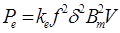 (Eq. 3.3)
where Pe is the eddy current loss in watts (W), ke is the constant that depends on the conductivity of the magnetic material, f is the frequency in hertz (Hz), δ is the lamination thickness in meters, Bm is the maximum flux density in tesla (T) and V is the volume of the magnetic material in cubic meters (m3) [14].
The eddy current losses can be reduced by [13]:
· Using a high-resistivity core material
· Using a laminated core, in transformers and electric machines the parts that are made of magnetic core and carry time-varying flux are normally laminated.
Hysteresis loss
During a cycle variation of current i, there is a net energy flowing from the source to the coil-core assembly. This energy loss goes to heat the core. The loss of power loss in the core owing to hysteresis effects is called hysterisis loss.
By testing various ferromagnetic materials, Charles Steinmetz proposed that hysteresis loss can be expressed as [14]:
 (Eq. 3.4)
where Ph is the hysteresis loss in watts, kh is a constant that depends upon the magnetic material and n is the Steinmetz exponent.
Core loss
The hysterisis loss and eddy current loss are lumped together as the core loss of the coil-core assembly, and given by:
 (Eq. 3.5)
Design Variables
In the following section, all the parameters that are necessary to design and construct a generator will be discussed and variables such as generator diameter, length, etc. will also be calculated.
Speed of the generator
The annual mean wind speed at Ga-Rampuru is approximately 4m/s [11]. The rotor will rotate at the same speed as the wind turbine; therefore this means that the rotor will rotate at:

 = 250 rad/s = 2387.3 rpm
The rotor speed and the average frequency of the induced voltage are related by:
 (Eq. 3.7)
Since a two-pole machine will be designed, the frequency is calculated using equation 3.9 to be 39.79 Hz.
Rotor and Stator Core
A cylindrically shaped rotor will be appropriate for this design as it allows maximum flux distribution over the armature surface as the field coils are spread over the periphery of the rotor. This type of design also accommodates the use of small cylindrical magnets [11].
A low carbon steel core with low permeability will be used in this design as it was found in the recyclable materials found in the village. This type of steel is cheap and mostly available. Compared with other better and expensive steel such as silicon, cobalt, etc. this type of steel has a very high core loss. The steel saturation flux density Bsat is estimated from the BH curve to be 1.5T.
Rotor Diameter (D)
The rotor diameter must be greater than the rotor yoke height (Hry), shaft radius (Rshaft) and the radial magnet length (Lm) [10].
D = 2 Hry + 2 Rshaft + 2Lm (Eq. 3.8)
In this design, D is restricted by the magnet arc radius of 25mm. Therefore D will be 50mm.
Airgap Length
The airgap length has a minimum value limited by the manufacturing tolerances; this value is typically in the range of 0.3mm to 1mm. In this design 0.5mm is chosen to be the airgap length.
Generator Length
The generator length is estimated to be 95mm; this is approximated from flux required to give the output voltage of the generator.
Airgap Flux Per Pole
In a radial machine, the flux per pole is given by:
 (Eq. 3.10)
where B is the average airgap flux density, D is the rotor inner diameter, L is the generator length, Kst is the lamination stacking factor and p is the pole pairs.
For this design the average flux density per pole Bgav is equal to the peak flux density Bg since the magnet arc is close to 180 degrees. Therefore the peak airgap flux is estimated to be 0.5T at the airgap and Kst is assumed to be 0.97.
The airgap flux and the lamination stacking factors were estimated from the following dimensions of the loudspeaker magnet:
· Magnet arc = 180 mechanical degrees
· Inner radius = 8mm
· Arc radius = 25mm
· Magnet radial length = 4mm
· Area of one pole = 706.8 μm2
From the above magnet dimensions, the flux per pole in the machine is then estimated to be 1.16 mWb this value is calculated from equation 3.10.
Windings
The stators of most synchronous generators are wound with three distinct and independent windings to generate three-phase power [14]. A simple layer winding was used in this design. Slot per pole per phase was chosen to be 1 and the winding pitch was full pitch.
A. Types of winding
The preferred type of winding is distributed winding as it reduces harmonics and makes better use of the stator or rotor structure. The mmf induced in the airgap is not sinusoidal, to get a pure sinusoidal mmf the number of slots have to be infinity. This means that the distributed winding is expected to have some harmonics.
Induced voltage for the distributed windings is:
 (Eq. 3.11)
Kw is the winding factor and depends on the winding arrangements and has a value less than unity. Distribution factor Kd and a short pitch factor Kp reduces the winding voltage magnitudes but also reduces certain harmonics in EMF and MMF waveforms.
 (Eq. 3.12)
Distributed winding configuration has one slot per pole per phase and its winding factor is equal to 1.
B. Winding arrangement
Single layer winding, where each slot contains one coil side, will be used in this design as it is economical to manufacture and has simpler end connection. Emf and mmf can be modified to reduce harmonics. In a three phase system even harmonics do not appear due to the winding symmetry, the only visible harmonics are the belt harmonics.
C. Winding Pitch
Short pitch is the most commonly used type of winding pitch. It reduces the distorting harmonics and produces a truer sinusoidal wave. The length of the end connection is also reduced thereby saving copper and reducing copper loss in the coil.
The drawback of short pitch winding is that the induced emf in it is smaller than in a full-pitch coil. The reason is that the total flux linking the short-pitch coil is smaller than that of the full-pitch coil.
Number of turns
The number of turns per pole is estimated to be 60 turns from equation 3.11.
The design parameters discussed will be modelled in FEMM in the next chapter to induce the output voltage and flux of the generator.
Introduction
The investigation that will follow focuses on the effect of substituting standard commercial magnets with recyclable speaker magnets that were collected from a dumpsite in the village, to compare the performance of the generator in either case.
In this chapter, the two pole generator geometry discussed in chapter 3 will be modelled in FEMM to analyse the output induced voltage and the flux of the generator. The lua-script in FEMM is run and the rotor is rotated 360 electrical degrees, for the lua-script refer to appendix C1.
Initially, a choice was made of three typical commercial magnet grades. Neodymium-iron-boron NdFeB was chosen from the rare-earth magnet group. Alnico6 was chosen from the Alnicos and the last type was barium ferrite from the ferrite or ceramic group. Then the machine will be modelled using different types of commercial magnets to investigate the performance of the generator.
The author then proceeded to investigate the magnetic properties of the loudspeaker magnet. This was done so that the parameters can be modelled in the finite element package.
Finally a design using the loudspeaker magnets was modelled to explore the recycled generator output.
Two pole geometry
Table 4.1 below summarizes the generator specifications that were discussed in chapter 3. These parameters will be modelled in FEMM to view the output induced rms voltage and the flux.
| Quantity | Value |
| Frequency | 39.79Hz |
| Poles | 2 |
| Connection | Y |
| Diameter of Rotor | 50mm |
| Machine Depth | 15mm |
| Air gap length | 0.5mm |
| Turns per phase | 80 |
| Stator slots | 6 |
| Steel Core | 1020 steel |
Table 4.1 Data of designed PM machine
The design is modelled in FEMM and is illustrated in figure 4.1 below.
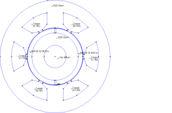
Figure 4.1 The generator modelled in FEMM
Commercial magnets
To investigate the performance of the generator, the author began by modelling the generator with standard commercial magnets with the properties given in table 3.1. The output rms emf and flux of the generator is tabulated in table 4.2 with different magnets that were used in the design.
Refer to appendix B for the graphs of the outputs. Matlab soft ware was used to draw the output rms emf and the flux, matlab code included in appendix C2.
Table 4.2 Generator output with commercial magnets
| Magnet | Type | Flux (Rms) | EMF (Rms) |
| Rare-Earth | NdFeb32 | 0.0459 | 9.4262 |
| Alnico | Alnoco6 | 0.0186 | 5.1619 |
| Ceramic | Ceramic8 | 0.0175 | 3.6075 |
Introduction
The following chapter outlines the steps that were taken in order to assemble the permanent magnet generator discussed in the previous chapters. This is done in order to compare the practical outputs of the generator with the simulated ones. The other reason is to investigate the performance of recyclable magnets with irregular shapes.
This investigation will only concentrate on assembling the generator part of the wind turbine system.
For the construction of the PM generator in this thesis two options were considered, the first was to collect readily available off-shelf materials to assemble a small generator. And the second was to convert an AC induction motor to a PM generator. Both options are discussed in this chapter.
Stator and rotor
The rotor rotates with the structure mount while the stator is fixed and mounted to a support structure. Since all these investigations were to be carried out under controlled laboratory conditions a drive and a frequency inverter which are readily available in the laboratory will be used to rotate the rotor at the desired speeds.
The drive will rotate the rotor and the induced voltage from the coils on the stator will be monitored by a voltmeter in the laboratory. Figure 6.2 illustrated this type of drive.
The size of the rotor in this thesis was constrained by the diameter of the recyclable speaker magnets. Therefore steel with this shape had to be found or cut to this shape. After finding the relevant steel, the cylindrical steel has to be drilled at the center.
Chapter 7. Conclusions
Based on the findings of the report, the following analyses and conclusions were drawn:
Resource assessment
Simulation results
It has been shown that a reasonable amount of power can be realised from a generator using recycled magnets from the dumpsites
Cost involved in the design
The overall cost of assembling this wind generator system will be very cost effective since all the materials are recycled from the village, and the entire system will be assembled by local artisans.
Validity of this thesis
Small power that can turn on small lamps will really be appreciated in this village as children will be able to study after sunset. This will clearly have a wide range of positive developmental benefits on this community.
Chapter 8. Recommendations
Based on the above conclusions, the following recommendations were drawn:
1. For a more accurate recyclable wind turbine design, all its components such as the drum, the tower, rotor disk and cables must be explored in depth. The following must be considered:
· Investigate how to extract maximum power from the wind using the drum, and how to prevent the drum from over spinning.
· How to use other irregular recyclable magnets in the village in the generator design.
2. Investigate how a permanent magnet generator topology can be changed or re-designed to accommodate the design of a generator with the shape of the loudspeaker magnets.
3. Look in to how the magnets can be removed from the speakers, since very strong clue is used to mount them, how this can be done in a cost effective way.
4. The axial flux permanent magnet topology should also be looked into to compare it to the radial flux type.
5. The exact costs of assembling and maintaining the recycled wind turbine should also be incorporated in the design procedure.
6. With the little output power generated in this thesis, this project must definitely be taken further to alleviate the electricity problems in South Africa.
References
1. Socio-economic rights project, “The right to affordable electricity” copyright @ community law centre 2002
2. IDASA, http://www.idasa.org.za
3. Department of Minerals and Energy, White Paper on the Renewable Energy Policy of the Republic of South Africa. August 2002
4. Department of Minerals and Energy, White Paper on the Renewable Energy Policy of the Republic of South Africa. November 2003
5. Sathyajith Mathew, “Wind Energy-Fundamentals, Resource Analysis and Economics ” © Springer- Verlag Berlin Heidelberg 2006
6. Smail Khennas, Simon Dunnett and Hugh Piggott, “Small wind systems for rural energy services”. ITDG Publishing 2003
7. Kevin Reeves, “The design and Implementation of a 6kW wind turbine simulator” University Of Cape Town, South Africa, Oct 2004
8. FrequentlyAskedQuestions http://www.magnetsales.com/Design/FAQs_frames/FAQs_2.htm © 2000 Magnet Sales & Manufacturing Company, Inc
9. R.C. Bansal, T.S. Bhatti, D.P. Kothari, “On some of the design aspect of wind energy conversion systems” Birla Institute of technology and science, Pilani, September 2002
10. Jacek F. Gieras, Mitchell Wing, “Permanent magnet motor technology-Design and Applications” 1st edition. Marcei Dekker, Inc. 1997
11. Prof E. J. Odendal, “Design, construction and testing of a small wind generator with electronic controller for domestic use”. University of Natal, Durban
12. Jacek F. Gieras, Mitchell Wing, “Permanent magnet motor technology-Design and Applications” 2nd edition. Marcei Dekker, Inc. 1997
13. P.C. Sen, “Principles of electric machines and power electronics” 2nd edition. John Wiley & Sons
14. Bhag S. Guru, Huseyin R. Hiziroglu, “Electric Machinery and Transformers” 3rd edition. Oxford University Press, Inc. 2001
15. Dr. James Livingston, “Magnetic Materials Overview”
16. E. Muljadi, C.P. Butterfield, Yih-Huei Wan, “Axial flux, Modulator, Permanent-Magnet with a Toroidal winding for wind turbine applications”. Cole Boulevard, Nov 1998
17. Magfag, 2003 by Force Field
18. M.A. Khan, P. Pillay, “Design of a PM wind generator, optimised for energy capture over a wide operating range”
19. Joe Naylor, “Speakers with Alnico magnets vs. speakers with ceramic magnets”
20. Hybrid (Wind/Solar/LP Gas) Systems for Rural Community Development, “Electrifying South Africa for prosperity and development”. Upper Maphaphethe by Mike Wintherden
21. Danish Wind Industry Association, ‘Guided Tour’ online htt://windpower.org/en/tour/wres/betz.htm
22. Lysen, E.H., ‘Introduction to Wind Energy’ CWD,2nd edition, p.p 51-73
23. Ripinga Nonkululeko, “Comparison of grid and off-grid rural electrification, based on the actual installation in Limpopo Province”. University of Cape Town, Oct. 2005
24. Alfred Still & Charles S. Siskind, “Elements of electrical machine design”. 3rd edition. McGraw-Hill Book company,inc. 1954
Appendix A
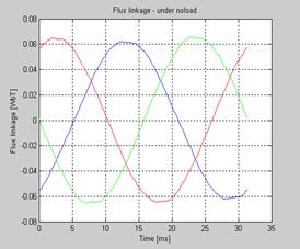
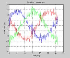
Graphs of output rms induced voltage and flux of the generator
1. Commercial Standard Magnets
a) Ceramic FLux_RMS = 0.0175
EMF_RMS = 3.6075
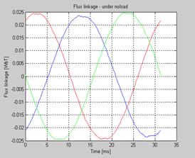
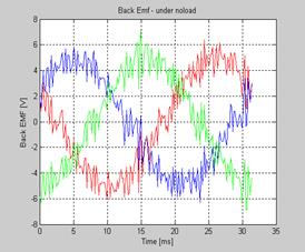
b) Alnico FLux_RMS =0.0168
EMF_RMS = 5.1619
c) NdFeB FLux_RMS = 0.0459
EMF_RMS = 9.4262
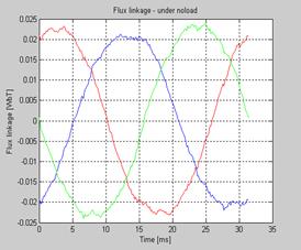
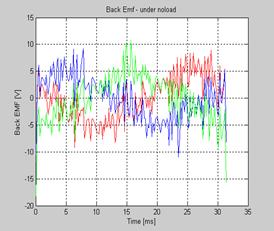
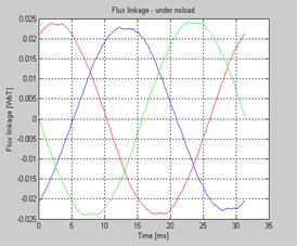
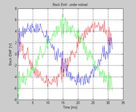
2. Loud Speaker Magnet
FLux_RMS = 0.0171
EMF_RMS = 3.4987
Appendix B
Matlab code for sketching the output emf and flux of the generators
% EMF calculation from FEMM
%By Maribini Manyage
clc
clear all; close all;
P = 2;
w = 1912; %mechanical speed in rpm
freq = (w*pi/30)*P/(4*pi); %frequency
XA = load('flux_link_A.txt');
XB = load('flux_link_B.txt');
XC = load('flux_link_C.txt');
beta = XA(:,1); % angle between Is_r and d-axis [elec degrees]
alpha = beta - beta(1,1); % Rotor position in [elec degrees] from Zero
time = alpha*(pi/180)/(2*pi*freq);%*1000; %time
flux_link_A = 2*XA(:,2);
flux_link_B = 2*XB(:,2);
flux_link_C = 2*XC(:,2);
% Perform spline in order to differentiate flux linkage vs time
pp_flux_A = spline(time,flux_link_A);
pp_flux_B = spline(time,flux_link_B);
pp_flux_C = spline(time,flux_link_C);
% extracting piecewise polynomial coefficients and derivation
[hgt,wdth] = size(pp_flux_A.coefs);
clear AA;
for k = 1:hgt
AA(k,:) = polyder(pp_flux_A.coefs(k,:));
end
dpp_flux_A = MKPP(time,AA)
[hgt,wdth] = size(pp_flux_B.coefs);
clear AA;
for k = 1:hgt
AA(k,:) = polyder(pp_flux_B.coefs(k,:));
end
dpp_flux_B = MKPP(time,AA);
[hgt,wdth] = size(pp_flux_C.coefs);
clear AA;
for k = 1:hgt
AA(k,:) = polyder(pp_flux_C.coefs(k,:));
end
dpp_flux_C = MKPP(time,AA);
%back emf
emf_A = ppval(time,dpp_flux_A);
emf_B = ppval(time,dpp_flux_B);
emf_C = ppval(time,dpp_flux_C);
figure(1);
plot(time*1000,flux_link_A,'r-');
hold on;
plot(time*1000, flux_link_B,'b-');
plot(time*1000, flux_link_C,'g-');
title('Flux linkage - under noload');
xlabel('Time [ms]'),ylabel('Flux linkage [WbT]')
grid;
figure(2);
plot(time*1000,emf_A,'r-');
hold on;
plot(time*1000, emf_B,'b-');
plot(time*1000, emf_C,'g-');
title('Back Emf - under noload');
xlabel('Time [ms]'),ylabel('Back EMF [V]')
grid;
x = length(flux_link_A);
FLux_RMS = norm(flux_link_A)/sqrt(x)
y = length(emf_A);
EMF_RMS = norm(emf_A)/sqrt(y)
Planning of mobile complete set for a rural wind generator
Abstract
The aim of this thesis is to alleviate the chronic lack of electricity supply in the rural South African areas by designing a portable wind generator kit.
An extensive assessment on the rural village of Ga-Rampuru, in Limpopo Province, was conducted, to investigate the present needs, as well as the availability of resources both human and material that would be needed to construct and assemble the system. From the inventory of recyclable materials found during the investigation the author was more inclined to suggest the design of a wind turbine that could be assembled and maintained by the local artisans.
A two pole permanent magnet synchronous generator was designed using standard commercial magnets, which were later replaced by recyclable loudspeaker magnets that were found in the village. This was done to compare the output of the generator in both cases. All the designs were modelled in FEMM, a software package, to estimate the induced voltage and flux of the generators.
Using standard commercial magnets the simulated voltage and flux levels were 9.4, 5.1, 3.6V and 0.0489, 0.0186, 0.0175 Wb, respectively. Assuming a generator current rating of 1 amp this would yield 36 watts at the estimated average wind speed of 4 meters per second.
Then when these were substituted with recycled speaker magnets the generator yielded a voltage of 3.5V and a flux of 0.0171Wb. The estimated output power of the recycled generator was estimated to be 10.5W. This compared well with the power output from the commercial magnets generators.
From these preliminary results it is quite apparent that a viable generator can be designed from the recyclable magnetic components. The same design procedure as outlined in this thesis can be used to design larger recycled generators with larger outputs. The design of this wind turbine will obviously have a wide range of positive developmental benefits on the community of Ga-Rampuru.
The next stage was practical construction to validate of the simulation results. This however could not be realised in time.
Chapter 1. Introduction
The subject of the report
The aim of this thesis is to design a simple wind generator kit that can be easily assembled and installed by rural artisans. The kit will use recyclable materials that are found in the rural areas to ensure a cost effective and environmentally sustainable solution.
Дата: 2019-07-24, просмотров: 295.