Background on wind energy
Wind powered systems have been widely used since the tenth century for water pumping, grinding grain and other low power applications [9]. Since then, this has lead to an investigation and attempt to build large wind energy systems to generate electricity.
Wind energy has proven to be cost effective and reliable in the past years. The main development of this technology has been with large wind turbines in the industrialized world, but there is scope to deliver decentralized energy service in the rural areas of developing countries [6].
Furthermore, wind energy is an attractive option to generate electricity since it does not consume fossil fuels nor emit greenhouse gases. The land on which the wind generators are build may also be used for agricultural purposes such as ploughing the land or domestic animal gazing.
During its transition from the earlier day’s wind ‘mills’ to the modern electric generators, the wind energy conversion systems (WECS) have transformed to various sizes, shapes and designs, to suit the applications for which they are intended for [5]. In this chapter, the main components of a simple small wind generator will be investigated and a wind generator suitable for Ga-Rampuru village will be designed using recyclable materials found in the area.
The available wind resource is governed by the climatology of the region concerned and has a large variability from one location to the other and also from season to season at any fixed location [9]. Hence, it is important that the wind generator is designed for a specific area; this will ensure that the wind energy in that specific area is exploited to generate maximum power from the wind.
Wind turbine basic principles
The wind generators are specially designed and build to extract power from turning blades with the maximum efficiency and minimum complexity [6]. The magnet rotor disk rotates as a result of the force of the wind on the turbine’s blades.
A typical small wind generator consisting of blades, tower, PM generator and the cabling is illustrated in figure 2.1. The main components, which are common to most wind generators, will be discussed below.
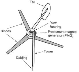
Fig 2.1 Basic features of a typical small wind generator [6]
The blades
Modern wind turbine rotors usually have two or three wooden blades. A larger number of blades would create more turning force (torque), but would not be capable of driving the PM generator fast enough to generate the required voltage, because the rotor would turn more slowly [6]. The rotor blades are designed in such a way that they extract the maximum power from the wind.
Power supplied by the blades to the generator is [7]:
 (Eq 2.1)
where  is the air density (Kg/m3), C is the dimensionless power coefficient and A the area swept by the blades in m3.
In equation 2.1 above, the power drawn from the wind is proportional to the cube of the wind speed. This means that if the wind speed doubles, there is 8 times as much power available from it [7].
A further important parameter is the tip speed ratio. The tip speed ratio is defined as the ratio of the tip of the blade to that of the undisturbed wind velocity entering the blades [11]. The ratio is given by [7]:
 (Eq 2.2)
where R is the radius of the blades, ωr is the rotor speed in rad/s and W the wind speed (m/s).
Multi bladed rotors operate at low tip speed ratios of 1 or 2, where else, one, two or three bladed rotors operate at higher tip speeds of 6 to 10. The power coefficient in equation 2.1 depends on tip speed ratio as shown in figure 2.2. For a particular wind rotor design there exists a tip speed ratio which will produce the maximum value of power coefficient [11].
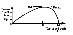
Fig. 2.2 Power coefficient Cp versus tip speed ratio [11]
Permanent magnet generator
Using permanent-magnet generators for small wind turbines is very commonly used world wide. Usually an AC generator with many poles operates between 10-100 Hz. Many configurations use surface mounted three phase permanent magnet synchronous generators with a rectifier connected to the generator terminals. [16]
A simple PM generator consists of the stator, magnet rotor disk and a shaft. The magnet rotor disk is mounted on a bearing hub so that it can rotate on the shaft due to the rotating blades of the wind generator.
The stator has coils of copper wire wound around them, which are accommodated in the slots. Electricity is then generated when the magnets on the rotor disks rotate past the coils embedded in the stator. The magnetic field that is created induces a voltage in the coils [6].
Rotor design
There are two types of rotor configurations commonly used world wide, these are the disk and the cup as shown in figure 2.3 below [20].
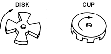
Fig. 2.3 Disk and cup rotor designs
The radius of the rotor primarily depends on the power expected from the turbine and the strength of the wind regime in which it operates [5].
Tower
The main function of the tower is to raise the blades and the generator to a height where the wind is stronger and smoother than the ground level. The wind speed increases with height because of the earth surface [9]. The tower should be high enough to avoid any obstacles such as trees, building, etc. Practical considerations such as expense, safety and maintenance limit the tower to between 10m to 20m [6] above ground level.
Дата: 2019-07-24, просмотров: 284.