If we allow one AC signal to deflect the beam up and down (connect that AC voltage source to the “vertical” deflection plates) and another AC signal to deflect the beam left and right (using the other pair of deflection plates), patterns will be produced on the screen of the CRT indicative of the ratio of these two AC frequencies. These patterns are called Lissajous figures and are a common means of comparative frequency measurement in electronics.
A
If the two frequencies are the same, we will obtain a simple figure on the screen of the CRT, the shape of that figure being dependent upon the phase shift between the two AC signals. Here is a sampling of Lissajous figures for two sine-wave signals of equal frequency, shown as they would appear on the face of an oscilloscope (an AC voltage-measuring instrument using a CRT as its “movement”). The first picture is of the Lissajous figure formed by two AC voltages perfectly in phase with each other.
B
If the two AC voltages are not in phase with each other, a straight line will not be formed. Rather, the Lissajous figure will take on the appearance of an oval, becoming perfectly circular if the phase shift is exactly 90o between the two signals, and if their amplitudes are equal
C
Finally, if the two AC signals are directly opposing one another in phase (180o shift), we will end up with a line again, only this time it will be oriented in the opposite direction
D
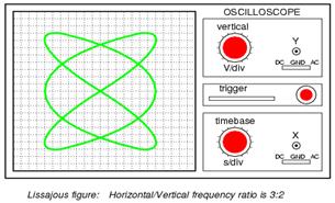
When we are faced with signal frequencies that are not the same, Lissajous figures get quite a bit more complex. Consider the following examples and their given vertical/horizontal frequency ratios
E
The more complex the ratio between horizontal and vertical frequencies, the more complex the Lissajous figure. Consider the following illustration of a 3:1 frequency ratio between horizontal and vertical
F
…and a 3:2 frequency ratio (horizontal = 3, vertical = 2)
In cases where the frequencies of the two AC signals are not exactly a simple ratio of each other (but close), the Lissajous figure will appear to “move,” slowly changing orientation as the phase angle between the two waveforms rolls between 0o and 180o. If the two frequencies are locked in an exact integer ratio between each other, the Lissajous figure will be stable on the viewscreen of the CRT.
The physics of Lissajous figures limits their usefulness as a frequency-comparison technique to cases where the frequency ratios are simple integer values (1:1, 1:2, 1:3, 2:3, 3:4, etc.). Despite this limitation, Lissajous figures are a popular means of frequency comparison wherever an accessible frequency standard (signal generator) exists.
Picture 1 Picture 2


Picture 3 Picture 4


Picture 5 Picture 6

Look at the pictures again and try to describe them without using the text.
16. Write a short essay on the topic: “Frequency measurement”
Unit 8
DISTANCE MEASUREMENT
Practice reading the following words and word combinations.
Three-dimensional, spatial, generalization, facilitating, simultaneously, digitize, positioner, repeatability, three-dimensional, spatially, technique, ambient, variable, resolvable, ground-penetrating, homogeneous, predictable, triangulation, disparity, vicinity.
What do you know about distance measuring techniques? Discuss in groups.
Read and translate text A.
4. Find in the text English equivalents to the following words and word- combinations:
Одномірний, трьохмірний, розподіл у просторі, вихідне положення, товщиномір, циферблатний індикатор, кардан, позиціонер, рука шарнірної конструкції, оцінка, вимірювати, правило масштабування, вимоги до проставлення розмірних допусків, велика кількість даних, непроникний, повторюваність, система вимірювання відстані, точка вимірювання.
TEXT A
Distance measurement, at its most basic, is concerned with determining the length of a unidimensional line joining two points in three-dimensional space. Oftentimes, a collection of distance measurements is called for, so that the shape, the orientation, or the changes in position of an object can be resolved. Therefore, one must consider not only the measurement of distances, but also their spatial and temporal distributions. Range measurement devices may be classified according to some basic distinctions. Generalizations can be made based on these broad classes, thereby facilitating the process of comparison and selection. The following subsections identify the fundamental bases for classification.
Contact or Noncontact
A common approach to measuring the distance to a point on an object is through a calibrated mechanical device that simultaneously connects the selected point to a reference position. Any tape measure, feeler gage, or dial gage may be considered an example of a simple contacting measurement device. Mechanical/electronic devices are available that allow a user to “digitize” discrete point positions on a three-dimensional surface. A gimbaled probe on the end of an X-Y-Z positioner or articulated arm is used to touch a specific point, and sensory information of the linear positions or joint articulations provide an accurate position estimate. Mechanical, contact-based methods are widely used in industry and can be extremely accurate. Some coordinate measuring machines (CMMs), for example, can achieve 1mm repeatability.
The chief disadvantage of mechanical approaches is that they are usually restricted to distances and work volumes up to a few meters at maximum. This is due to fundamental scaling laws for mechanical structures. As the requirement to span larger distances increases, the mass and mechanical tolerancing requirements on the machine make designs impractical. Also, mechanical approaches are too slow to make multiple measurements in rapid succession, as is typically required in range imaging or position tracking, when the measurement involves large sets of spatially or temporally distributed data.
Noncontact techniques for performing ranging, range imaging, and position tracking are many and varied. In the centimeters to meters range, most do not approach the accuracy of CMMs; but at larger scales and for large quantities of data, they become a practical necessity. The rest of this chapter will review noncontact approaches only.
Active or Passive
Noncontact distance measurement may be divided into active or passive techniques. Active techniques involve some form of controlled energy (field or wave) linking a known reference location to the unknown target location. The source of energy is typically associated with the reference location, but in some cases the target, or both target and reference, may be active. Passive techniques rely on an externally occurring source of energy (e.g., sunlight or target/background temperature contrast) to make the target detectable.
An active approach can often simplify the distance measurement problem because it allows a greater degree of control over the many factors that can influence a measurement. For example, the choice of the form of energy and the power level of the active source can minimize the effect of uncontrolled variables like ambient illumination, weather, and atmospheric conditions. Furthermore, an active approach provides an opportunity to selectively localize the measurement spatially and temporally, eliminating possible ambiguity about which target point was measured at a given time. In contrast, passive systems (e.g., stereo ranging) sometimes suffer from the so-called “correspondence problem,” which is concerned with how to determine whether a given target point, detected from two or more viewpoints, or over two or more instants, is in fact the same physical point.
A common use of active approaches is to make range measurements “through” materials that are mechanically or optically impenetrable. Examples include medical imaging, where various forms of directed energy (ultrasound, X-rays) are used to build surface or volumetric maps of organs and bones; sonar, which penetrates water better than light does; and ground-penetrating radar, which can detect objects and their depth beneath ground surface.
Passive approaches, while not offering the same range of control and flexibility of active approaches, offer certain advantages. First, because they emit no energy, their existence cannot be detected by another remote detection system. This feature is very important in military applications. Second, passive systems can often collect multiple point range measurements more quickly because they are not limited by the
rate at which they can direct an energy source toward a target point, as is the case with most active systems. For example, a stereo ranging system effectively collects all resolvable target points in its field of view simultaneously, while a scanning laser, radar, or sonar ranging system collects each measured point sequentially. Finally, the absence of a directed energy source is a simplification that can significantly reduce the size, cost, and hardware complexity of a device (although at the expense of increased signal processing complexity).
Дата: 2016-10-02, просмотров: 350.