Usually the main part of Patent Specifications consists of the following communicative blocks:
ü Cross-references or statement concerning federally sponsored research;
ü Field of the invention to which it is related to;
ü Background of the invention or description of the Prior Art (the block describes the previous inventions in a particular field or the technical problem solved by the inventor);
ü Summary of the invention (it is a brief description of the invention features. It also can include the objects of the inventions);
ü Broadening paragraphs (the aim of it is to broaden the scope of the invention and the rights of the inventor);
ü Brief description of the drawings
ü Detailed description of the invention with references to the drawings;
ü Description of the preferred embodiments;
ü Operation;
ü Another broadening paragraphs;
ü Claims.
However, there are no strict requirements to include all these blocks into the Patent Specifications. They can be either omitted or inserted. The Claims are believed to be one of the most important blocks of the Patent Specifications. They define the spirit of the invention and its scope. It should be mentioned that they have the juridical meaning and legal force. A patent claim is traditionally written as a single sentence in most jurisdictions. Each of these “sentences” is preceded by a number that becomes the claim’s identifier, e.g. “Claim 1.” Claims also can be introduced in the text of the Patent Specifications with the following expressions:
- I claim that … / we claim that …;
- What I claim is … / what we claim is …;
- Claims are…
Usually Patent Claim has three parts:
- Preamble;
- Linking words (transitional phrases);
- Main part (body of the claim).
As it is said above the Claims are very crucial part of the Patent Specifications and translation of them must be performed carefully and precisely.
More information: http://www.patentwire.eo.in/images/guidelines.pdf
Task 1. Look through the suggested GB and US Patent Specifications and find all the Bibliographical Information out.
Task 2. Pay attention to the difference of the structures of GB and US Patent Specifications.
Example of the text of earlier GB Patent Specification.
Text of the invention description to the GB Patent № 793 414
«Bollard with a Detachable Post» (invented by Jacques Genot)
PATENT SPECIFICATION 793, 414
Date of Application and Filing Complete Specification : August 8, 1956.
No. 24283/56.
Application made in France on August 8, 1955.
Complete Specification Published April 16, 1958.
Index at Acceptance:– Class 113, C36A.
International Classification:– B63b.
COMPLETE SPECIFICATION
Bollard with a Detachable Post
I, Jacques Genot, of Villa Bagatelle, Rue Louis Pardonnet, Montbeliard, Doubs, France, of French Nationality, do hereby declare the invention, for which I pray that patent may be granted to me, and the method by which it is to be performed, to particularly described in and by the following statement:–
Mooring bollards for ships are generally constituted by a metal base member deeply secured in the quay with an upper projecting post intended to receive mooring ropes.
Bollards must be renewed from time to time and such replacement is long and onerous work and requires immobilization of the quay because of the necessary digging out, demolition of the reinforced concrete and casting of cement to hold the base of the new bollard.
The object of the present invention is to provide an improved construction of bollard having a removable and replaceable post, whereby once the base has been grouted and anchored in the quay it need not thereafter be disturbed when the post is renewed.
According to the present invention, a bollard comprises a base of cast steel for grouting into a cavity in a quay, said base having a series of intercommunicating holes to facilitate insertion of grouting material, a circular recess in the upper part of the base, a post having a shoulder at its lower end adapted to seat into said recess, corresponding holes in the shoulder and in the base, and bolts engaged through said holes for bolting the post to the base.
The base advantageously has a central aperture in its upper part leading to the intercommunicating holes, thereby to facilitate insertion of grouting material into and about the base after the latter has been placed in position in the quay.
To prevent accumulation of water inside the base, a lead lining washer may be inserted in the recess of the base and be aperture to form a close fit about the stems of the bolts.
For convenience of holding the bolts, the base may have a circular radial recess to receive and hold the head of the bolts positioned with their stems upwardly.
The accompanying drawing illustrates an example of construction of bollard in accordance with the invention.
In this drawing: –
Fig. 1 shows the base of the bollard in longitudinal section.
Fig. 2 represents the post in central vertical section.
The base 1, Fig. 1, is preferably made of cast steel for securing in the concrete of the quay.
A series of intercommunicating holes 2, 3, 4, 5 permits filling with cast binding material in the opening 6 during positioning of the base in the quay.
The upper part 7 coming on a level with the quay comprises a circular throat 8 having holding bolts 9 the heads of which are solidly anchored in the metallic mass and the stem 10 of which passes upwardly through a lining 12 of lead. The tightening nut 13 is disposed in the circular recess 14 intended to receive the base of the post.
The post (Fig. 2) is formed by a hollow column 15, the base 16 of which is of a diameter corresponding to the recess 14. The base 16 is provided with a series of holes 18, 19 the diameter of which corresponds to that of the stems of the bolts 10.
Recesses 20, 21 are provided to receive the tightening nuts 13.
The advantages of this bollard will now be apparent.
3. Examples of the text of the US Patent.
UNITED STATES PATENT [12] [10] Patent No.: US 8,313,214 B2
Liang et al. [45] Date of Patent: Nov. 20, 2012
[54] DOUBLE-SIDED LED LAMP
[75] Inventors: Kun Liang, Shenzhen (CN); Ting Dong, Shenzhen (CN); Jian Yuan,
Shenzhen (CN)
[73] Assignees: Hong Fu Jin Precision Industry (ShenZhen) Co., Ltd., Shenzhen,
Guangdong Province (CN); Hon Hai Precision Industry Co., Ltd.,
Tu-Cheng, New Taipei (TW)
[*] Notice: Subject to any disclaimer, the term of this patent is extended or adjusted
under 35 U.S.C. 154(b) by 221 days.
[21] Appl. No.: 12/882,155
[22] Filed: Sep. 14 , 2010
[65] Prior Publication Data
US 2011/0176303 A1 Jul.21, 2011
[30] Foreign Application Priority Data
Jan. 18, 2010 (CN) ……………………….. 2010 1 0300396
[51] Int.Cl………………………………………..F21V 1/00 (2006.01)
F21V 13/10 (2006.01)
[52] U.S. Cl. ……………………………362/235; 362/246; 362/307; 362/311.02
[58] Field of Classification Search …………….362/235-237, 362/245, 246,307, 311.02, 311.04
See application file for complete search history.
[56] References Cited
U.S. PATENT DOCUMENTS
4,345,308 A * 8/1982 Mouyard et al. …………………….. 362/332
4,922,384 A * 5/1990 Torrence ..........................................362/611
6,561,689 B1 * 5/2003 Kidd et al. ........................................362/541
6,729,746 B2* 5/2004 Suehiro et al. .....................................362/241
6,948,838 B2* 9/2005 Kunstler .............................................362/545
7,654,689 B2* 2/2010 Chang .................................................362/248
7,815,355 B2* 10/2010 Thompson et al. ................................362/560
7,883,232 B2* 2/2011 Bang ....................................................362/97.3
FOREIGN PATENT DOCUMENTS
TW 200622430 A 7/2006
TW 200708843 A 3/2007
* cited by examiner
Primary Examiner – Alan Cariaso
[74] Attorney, Agent, or Firm – Altis Law Group, Inc.
[57] ABSTRACT
A double-sided LED lamp includes a shell, a plastic circuit board (PCB) and an optical film. The shell is made of translucent or transparent material. The PCB includes a number of rows of LEDs for emitting light beams, and defines a number of rows of through holes. The optical film facing the LEDs can reflect some of the light beams through the number of holes and also allow some of the light beams to pass through.
Figures
Patent Specification
BACKGROUND
1. Technical Field
The present disclosure relates to light-emitting diode (LED) lamps, especially to a double-sided LED lamp which can emit light from two sides.
2. Description of Related Art
A light-emitting diode (LED) lamp often includes a LED light-source module. The luminous angle of a single LED light-source module is narrow and limited. When a larger angle or more than one area needs to be lit, then several LED light-source modules must be used.
BRIEF DESCRIPTION OF THE DRAWINGS
Many aspects of the embodiments can be better understood with reference to the following drawings. The components in the drawings are not necessarily drawn to scale, the emphasis instead being placed upon clearly illustrating the principles of the embodiments. Moreover, in the drawings, like reference numerals designate corresponding parts throughout the several views.
FIG. 1 is an exploded view of a double-sided LED lamp according to an exemplary embodiment.
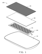
FIG. 2 is another exploded view of the double-sided LED lamp of FIG. 1 viewed from another viewpoint.
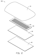
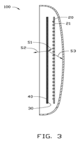
FIG. 3 is a schematic view illustrating the light path of the double-sided LED lamp.
DETAILED DESCRIPTION
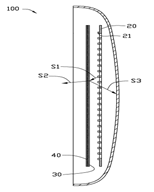
Referring to FIGS. 1-2, a double-sided light-emitting diode (LED) lamp 100 according to an exemplary embodiment includes a shell 10, a printed circuit board (PCB) 20, and an optical film 30. The shell 10 can be made of translucent or transparent material.
The PCB 20 is disposed in the shell 10 and includes a plurality of rows of light-emitting diodes 21 facing the optical film 30. The PCB 20 defines a plurality of rows of holes 22, which allows the reflected light beams from the optical film 30 to pass through. The rows of the light-emitting diodes 21 and the rows of the holes 22 are alternately arranged.
The optical film 30 can reflect some light beams and also allow some light beams to pass through. Portions of the light beams from the light-emitting diodes 21 can be reflected by the optical film 30 and travel to the translucent or transparent shell 10 through the holes 22. The optical film 30 can be a transflective sheet or a brightness enhancement film (BEF).
The double-sided LED lamp 100 further includes a diffusion sheet 40. The diffusion sheet 40 is used to diffuse the light beams from the LEDs 21. The diffusion sheet 40 is mounted on one side of the optical film 30 and faces away from the circuit board 20.
Referring to FIG. 3, the light beam S1 from the LED 21 travels to the optical film 30 first. A portion of the light beam S1, i.e., the light beam S2 passes through the optical film 30 and the diffusion sheet 40, and comes out of the shell 10. The rest of the emitted light S1, i.e., the light beam S3 is reflected by the optical film 30. The reflected light beam S3 passes through the holes 22, and travels to and passes through the shell 10. With such structure, opposite sides of the double-sided LED lamp 100 can emit light.
It is to be understood, however, that even though numerous characteristics and advantages of the present disclosure have been set forth in the foregoing description, together with details of the structure and function of the present disclosure, the present disclosure is illustrative only, and changes may be made in detail, especially in matters of shape, size, and arrangement of parts within the principles of the present disclosure to the full extent indicated by the broad general meaning of the terms in which the appended claims are expressed.
Claim
1. A double-sided LED lamp comprising:
· a shell made of translucent or transparent material;
· a plastic circuit board (PCB) comprising a number of rows of LEDs for emitting light beams, and defining a number of rows of through holes; and
· an optical film facing the LEDs to reflect some of the light beams through the number of holes and also to allow some of the light beams to pass through.
2. The double-sided LED lamp of claim 1, wherein the rows of LEDs and the rows of the holes are alternately arranged.
3. The double-sided LED lamp of claim 1, further comprising a diffusion sheet, wherein the diffusion sheet is mounted on one side of the optical film and faces away from the circuit board to diffuse some of the light beams from the LEDs.
4. The double-sided LED lamp of claim 1, wherein the optical film is a transflective sheet.
5. The double-sided LED lamp of claim 1, wherein the optical film is a brightness enhancement film (BEF).
[12] UNITED STATES PATENT [10] Patent No.: US 8,322,688 B2
Hebert [45] Date of Patent: Dec. 4, 2012
[54] LANDING JACK LIFT
[76] Inventor: Hebert, William (Reno, NV)
[*] Notice: Subject to any disclaimer, the term of this patent is extended or adjusted under 35 U.S.C. 154(b) by 119 days.
[21] Appl. No.: 12/717,945
[22] Filed: March 4, 2010
[65] Prior Publication Data
US 2010/0224842 A1 September 9, 2010
Дата: 2019-03-05, просмотров: 422.